
A large part of maximizing grip of the tires is Ackermann selection. Before we begin, we need to ask a few questions:
1. What state of the car do we design for?
2. How do we make our design robust to changes in vehicle state?
I've approached these questions below and detailed the entire selection/design process.
One of the most important elements to consider here is tire loading. Fz has a drastic effect on Fx and Fy, so I'm going to start by defining the normal loads we want to design around. In order to find these normal loads, I need to find representative accelerations and velocity. To do this, I've generated a GGV using UT's MMM implementation. I then calculated the frequency of points within that GGV and put this into a 2D format. I'm going to analyze the four highest frequency points, and I've pulled the range of velocities at which each point occurs (max and min values). This will give me 8 conditions to check. I've Included a picture of the frequency plot to the right.
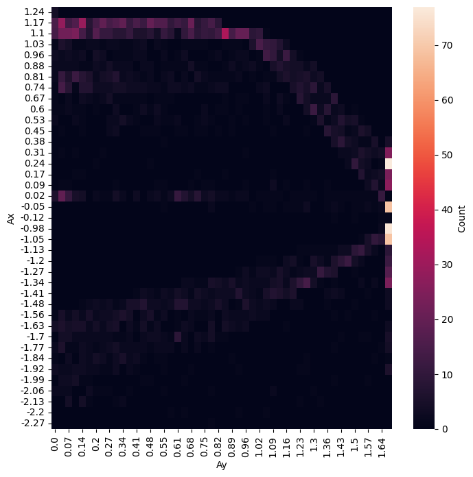
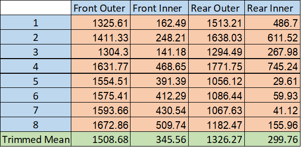
I'm using the following points from the frequency plot: (1.67, 0.24), (1.67, -0.05), (1.67, -0.98), (1.67, -1.05). Their respective min and max velocities are: (18.03, 22.19), (11.55, 27.6), (11.6, 13.14), (13.1, 17.76). Note that the accelerations are in gs, and the velocities are in m/s. I'm now using these 8 conditions and putting them into our loading spreadsheet to get the forces at the tires. Note that every force in the table is in Newtons.
I've generated graphs of Fy vs SA for each tire below. Note that the lighter, multicolored lines are the exact loading conditions for each tire, and the black lines are the result of the trimmed mean. I realize that using a trimmed mean may not be the best metric for this, but the peak Fy on the black lines looks very similar to that seen across the other normal loads.
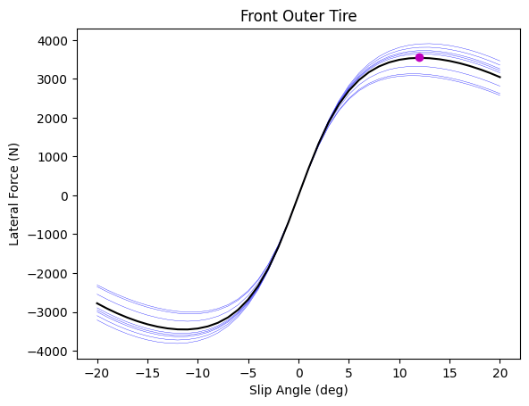
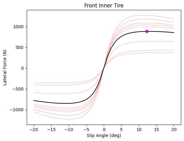
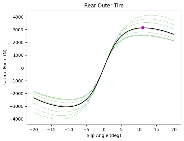
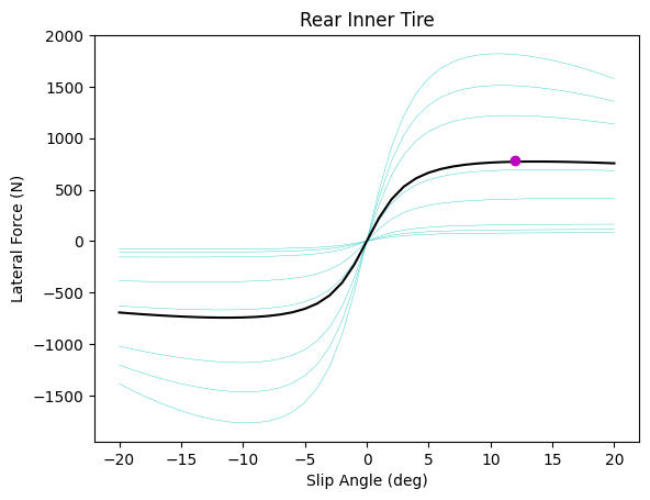
These plots also highlight how our Fy reaches a near maximum at lower SA for lower Fz. For instance, the peak for our front inner tire (using the trimmed mean) lies on a relatively horizontal line segment; we get a very similar lateral force for a large range of SA, starting around 7.5 deg. For this reason, I will take optimal SA for the inner tires as the lowest SA that still corresponds to a peak (at any Fz). This greatly increases Fy at higher Fz and has a slightly negative effect at lower Fz, but the gain at higher loads is greater in magnitude, and this makes performance less sensitive to Fz.
Our Ackermann selection directly influences the front slip angles, so I will only focus on the front tires for now. Based on the previous paragraph, I will select the optimal inner slip angle as 10.625 deg and the optimal outer slip angle as 11.875 deg. Also, note that I took values from the GGV earlier based on frequency. I've now gone back and pulled the average radius across our sampled points, and I will use this value for the Ackermann calculation. This radius is 14.102 meters.
I now have a set of targets to design around. I need my inner SA to be 10.625 deg, I need my outer SA to be 11.875 deg, and I'm designing with a 14.102m radius turn in mind. I'm now going to take these values, make a mockup of our 2023 concept vehicle in a 2D sketch, and analyze this sketch going forward.
I've included the applicable 2D sketch to the right. I set a radius of 14.102m at the CG, then I drew concentric circles concident with the inner and outer tires. From here I drew tangents to the inner and outer circles, defined SA, and took the angles between each wheel and the normal to the track (steered angle). This gives us our two steered angles and therefore our Ackermann percent. Inner: 14.05 deg, outer: 15 deg, Ackermann: -6.76%.
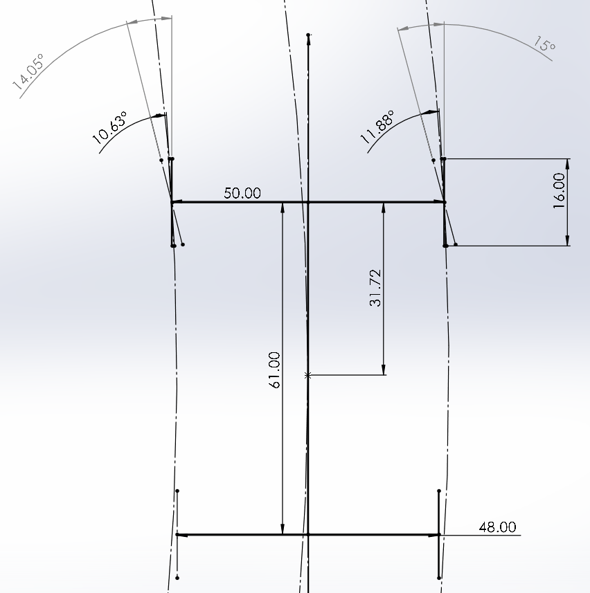
I've now modified the longitudinal position of the outboard tie rod mounts to reflect this Ackermann percent. The inner tire angle is 14.05 deg, and the outer tire angle is 14.99 deg at 56.25 deg of steered angle. Now that I've set the Ackermann percent, I need to check physical limitations regarding rules requirements (minimum turn radius).
FSAE rules specify that we must be able to complete a 4.5m radius turn. In order to check this condition, I need to find the max tire angles allowable by linkage clearance (control arms and tie rods). Note that the Ackermann percent above will influence the max possible tire angles.
After iterating through our dynamic reference sketch and checking CAD assemblies, I found that the max allowable wheel angles are 23.83 deg inner and 26.13 deg outer (under max heave/roll), occurring at 95 deg steered angle. Now we need to verify whether these angles allow us to complete our required minimum turn radius. I've created a new 2D sketch and mapped the IC, assuming a velocity low enough that no slip angles develop (worst case).
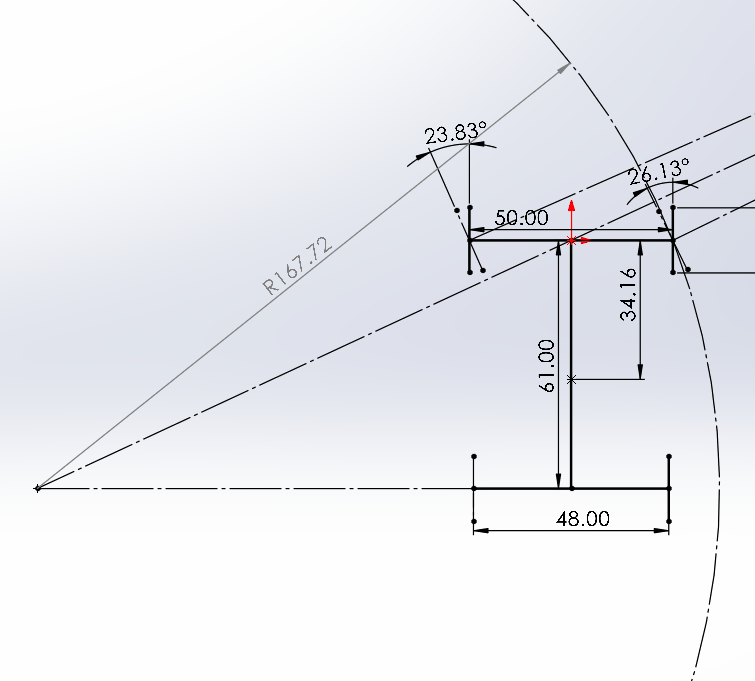
From the 2D sketch, we see that our minimum attainable turn radius is 167.72 in, or 4.26 m. Therefore, this specific steering design seems valid from a rules standpoint as well.