Now I can size the column tubes appropriately. I'll use the following formula for this calculation: shear stress =
Tr / Ip. I need a worst case torque through our system, so I will assume improper use of the steering wheel and
say that the max torque is a 150 lb person putting their full weight on the edge of the steering wheel. This gives
a torque of approximately 66.67 lbf-ft, and I'll approximate this to 70 lbf-ft). I realize this is likely a heavy
over-estimate, but the fact that we can only acquire tubes with discrete wall thicknesses lessens the extent of
weight gain. I'll opt with steel 4130 for now as our material (due to its yield strength and our team's familiarity
with it). This calculation gives me the following:
OD / (OD^4 - ID^4) ≤ 8.484
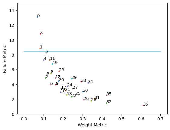
I also want to minimize mass, so I need to minimize OD^2 - ID^2. I've plotted failure metric vs weight
metric to the right. Point 4 corresponds to a tube of outer diameter 0.75" and inner diameter 0.68". However, I
calculated the bearing stress due to the bolt connection through the column, and the tube currently fails. Now
I'll increase inner diameter in discrete sizes until the tube doesn't fail. The new inner diameter is 0.652" (this
is point 8 on the scatterplot).

I repeated this process for the upper column, but we introduce a bending moment on the upper column. Therefore, I sized the upper column assuming a load of 150 lbf (driver weight) at the steering wheel. This accounts for a typical driver accidentally putting their full weight on the wheel. I then ran fea applying a force of 150 * 2 = 300 lbf on the upper column, directed horizontally. This should account for the force that arises from 2g decel, assuming the driver's full weight ends up on the steering wheel (also worst case).
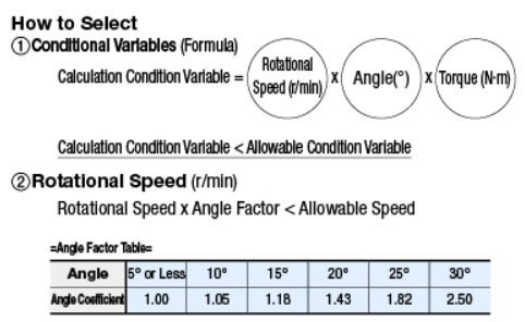
I now know the torque throughout the steering system, so I can select universal joints that meet my requirements. Note that I will use Misumi to source these u-joints, as they have highly adjustable components and in-depth data sheets. I've gone ahead and located a potential model (the standard model made by Misumi). I'll start at this arbitrary point and look at the selection criteria from the data sheet, listed to the right:

Using the given formula, I'll approximate an arbitrary rotational speed as 60 rpm (1 revolution per second). This is technically intermittent speed rather than continuous, but it'll give us a worst case scenario. Our u-joint angle is 25 degrees, and the torque is 70 lbf-ft (95 Nm). This gives a condition variable of 142,500 and a corrected rotational speed of 109.2 rpm. I've selected a u-joint with a condition variable of 175,000 and an allowable rotational speed of 900 (UNCA16). I've now implemented two of these into the design.